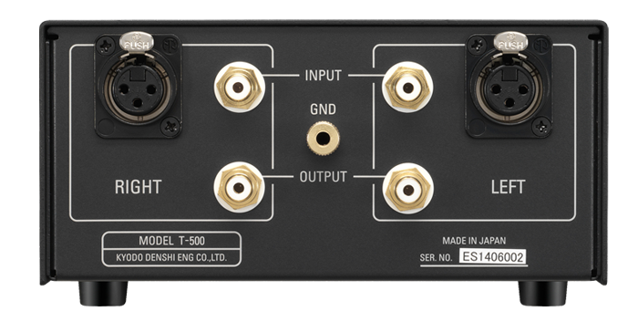
MC Stepup TransformerT-500
Recieved Prizes
Product Outline and Concept
We introduced the special coil winding structure used for T-1 (out of production) which established a very good reputation. Now we applied the technology for mass-production type MC Step-up transformer T-500 which we introduce this time. The merits of T-500 are its high sound quality and realization of low price.
Because a MC cartridge generates power through a coil, it conducts a “balance operation” at the both of beginning and end of winding. We release T-500 for high sound quality MC cartridge which has the input portion of “full balance correspondence” which optimize its specialty to the maximum.
Main features
1. Full Balance Type Input Portion
When generating power through a cartridge coil, a balance operation is conducted essentially.
Transmitting this signal with an unbalanced connection results in not only the merit of balanced type is damaged or lost, but also external noises directly affects sound quality.
The basis of wiring at the time of connecting T-500 by using a balanced phono cable is shown in Fig. 1. The signal is transmitted from the cartridge coil to the transformer coil through the push-pull balancing circuit and the shield earth covers them. Therefore, the negative effect caused by external noises can be fully blocked. In addition, the full balanced connection is structured for the cartridge side by connecting the center of primary coil of transformer to the minus point of secondary coil.
A general structure of connecting a step-up transformer for MC cartridge by using of an unbalanced phono cable is shown in Fig. 2. At the unbalanced connection composed of the signal wire and external shield, the shield side is exposed to the external noises. Therefore, it results in not only the induction noises affect it easily, but also the negative effect is invaded to the signal wire.
2. Adopting the High Performance Step-up Transformer having the Special Coil Winding
The excellent characteristics, the best lower-band-linearity in the market and the highest efficient step-up (low loss) in the market, have been achieved by winding the low loss extra-thick cupper wires (Primary: 0.32 dia., Secondary 0.12 dia.) around the gigantic EI core made of the “0.2mm thick 78% super permalloy core material”. Based on this technology, creation of lively sound over the all bands are realized.
We adopt the special divided coil winding structure developed by in-house, which is believed to be difficult unless produced with hand-made. The phase distortion in audible band has been reduced drastically and auditory lateralization has been clarified furthermore.
3. Materializing a Resonance Free and Vibration Free structure
The step-up transformer is supported with the polyethylene foam, which prevents it from conveying any outside vibration to inside the step-up transformer. A reproduced sound with good S/N impression has been realized.
For the chassis base and cover making of 1.2mm and 1.6 mm steel plates, copper plating and finishing are conducted. The parts are assembled with the stainless-steel non-magnetic screws to minimize the influence of the magnetic distortion; thereby the clear sound has been realized.
By adding a shield board at the center of chassis to divide the left from the right, the separation on audibility has been substantially improved.
Product Specification
Applicable Cartridge’s Output Impedance | 1.5 to 40 ohm |
Secondary Impedance Loading | 47 k-ohm |
Step-up Ratio ( voltage gain ) | 26dB |
Frequency Range | 10Hz to 50kHz (±2dB) |
Dimensions | W: 174mm H: 88mm D: 168mm |
Weight | 2kg |
Input/Output Terminals | Machined gold-plated terminal |